


DIY Mini Digital Oscilloscope Kit STC8K8A Microcontroller Electronic Soldering Practice Parts

 Direct purchase from the factory
Checkout garantit sikur

 Rigal b'xejn
 Politika tat-tbaħħir
 Politika tar-ritorn
Rigal B'Xejn
Merħba għal Roymall, is-sit professjonali tiegħek għal xiri ta' rigali ta' kwalità għolja. Napprezzaw is-sapport tiegħek u rridu nuruk gratitudni billi noffru rigal b'xejn ma' kull ordni.Politika tat-Tbaħħir
Oġġetti jintbagħtu fi żmien 2-5 ġranet tax-xogħol. Ordni ta' aktar minn $9.9 jintbagħtu b'xejn.1. Politika tar-Ritorn
Oġġetti jistgħu jintirbu sa 40 jum. Oġġetti personalizzati ma jistgħux jintirbu.2.Politika tar-Rifużjoni
Ir-rimi jintirbu bl-istess metodu ta' ħlas oriġinali.Feature:
>>>Manual: Click here to open<<<
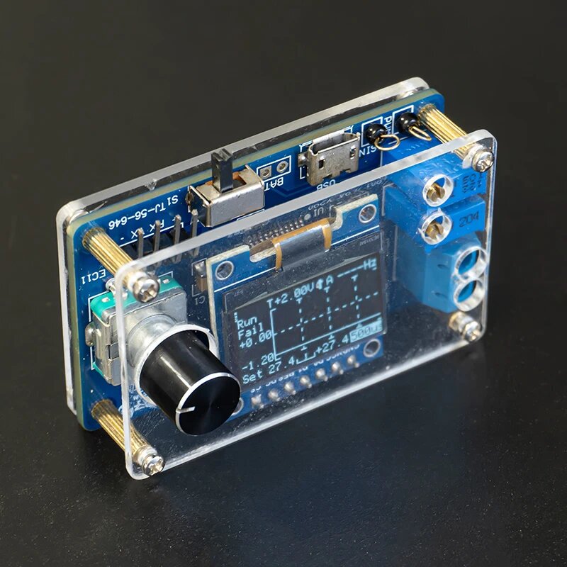
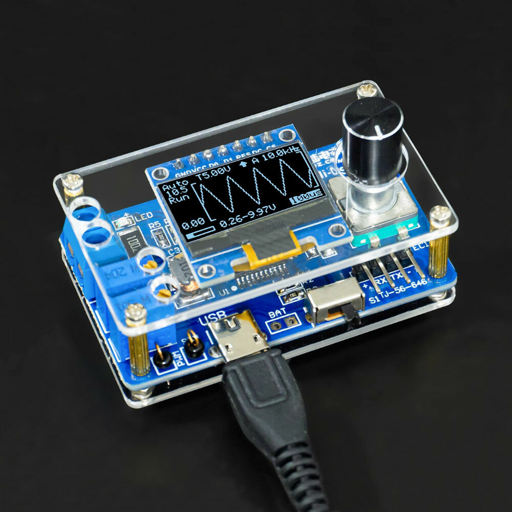
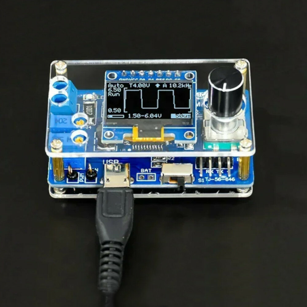
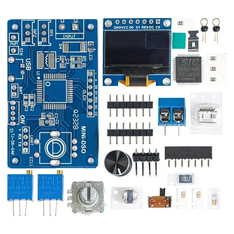
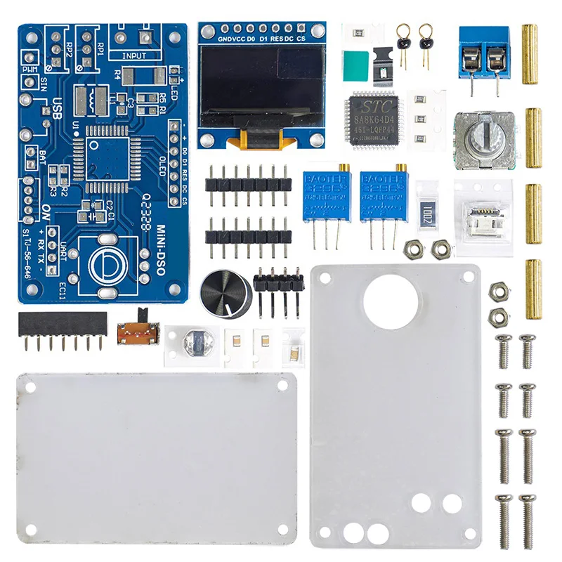
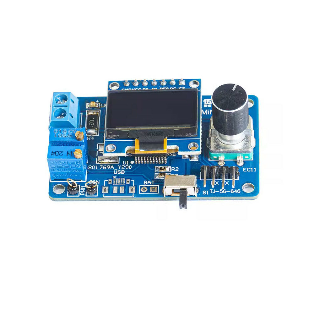
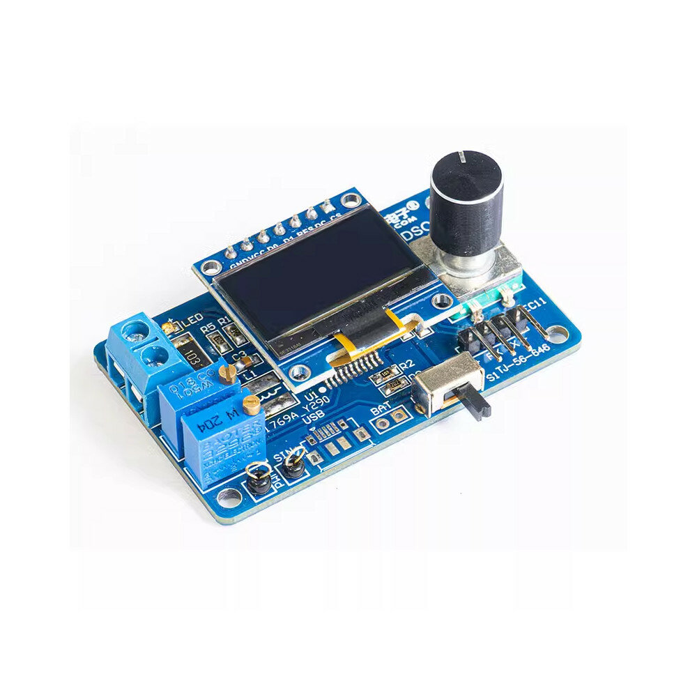
Product name: MiNi-DSO microcontroller oscilloscope kitProduct model: TJ-56-646PCB size: 57 * 34mmWorking voltage: 4-5VSingle chip: STC8A8K64S4A12Display: 0.96 inch OLED display screen -7P, 128 * 64 resolutionNumber of channels: single channelSec/div: 500ms, 200ms, 100ms, 50ms, 20ms, 10ms, 5ms, 2ms, 1ms, 500us, 200us, 100us (100us only available in automatic trigger mode)Voltage range: 0-30VSampling level: 10kHz@100us /DivTrigger level: Trigger voltage levelTrigger slope: u2191 - rising edge, u2193 - falling edge triggerTrigger mode: A-automatic mode, N-normal mode, S-single mode.
Description:
*Trigger level: For repetitive signals, the trigger level stabilises the display. For single-shot signals, the trigger level captures it.*Trigger Slope: The trigger slope determines whether the trigger point is on the rising or falling edge of the signal.*Trigger Mode:*Auto Mode: continuous scanning. Click the encoder to stop or run sampling. If triggered, the waveform will be shown on the display and the trigger position will be placed in the centre of the graph. Otherwise, the waveform will scroll irregularly and display "Fail".*Common Mode: After the pre-sampling is completed, you can input the signal. If triggered, the waveform will be shown on the display, waiting for a new trigger. If there is no new trigger, the waveform will be kept.*Single Mode: After the pre-sampling is completed, the signal can be input. If triggered, the waveform is displayed and the sampling is stopped. User needs single point encoder to start the next sampling.*When in common mode and single mode, make sure the trigger level has been adjusted correctly, otherwise the waveform will not be shown on the display.*Indicator light: Normally the indicator light is on to indicate that sampling is running. *Save Setup: When exiting the setup interface, all parameters of the setup interface and main interface will be saved in EEPROM.
Package includes:
Type1:
1 x DIY Kit
Type2:
1 x DIY Kit with shell


